I've been quiet, but busy -- with now just a few weeks until the raffle, construction of the raffle amplifier is now well underway.
Here's a link to the current schematic. There are a few component values that still remain to be tweaked, especially in the reverb/dry mix and tremolo sections, but it's close enough to the final that I've been using it as my working document.
I thought it might be useful to document my build process a little bit.
As usual, the starting schematic is drawn in LTSpice, a great freeware simulation package. Although I typically don't bother trying to simulate an entire amp of this complexity all at once, I do also make heavy use of LTSpice to simulate many of the individual subsections of the amplifier.
Once I have a schematic in-hand that is sufficiently fleshed out, I begin the process of laying out the design. I do this mainly with the excellent shareware DIY layout creator (DIYLC) software by Bancika, proprietor of the DIY-fever blog.
I use DIYLC to layout the individual boards, but also to get a good-enough idea of where all of the chassis-mounted components such as the transformers, tube sockets, and pots will go. The boards are fabricated more-or-less directly from images exported from DIYLC, but I typically will draw final drill plans for the chassis itself in another vector drawing program that is more purpose-built for that sort of thing.
Here's my overall rough layout in DIYLC as it stands right now:

I started with fabrication of the mainboard. To do this, I export a PNG image from DIYLC of the whole layout, then import it into a graphics program, then crop and scale the image to the actual size I want. I then print out this out (taping together pieces if it's larger than will fit on an 8.5"x11" paper), and tape the overlay onto G10 garolite that I have cut to size.
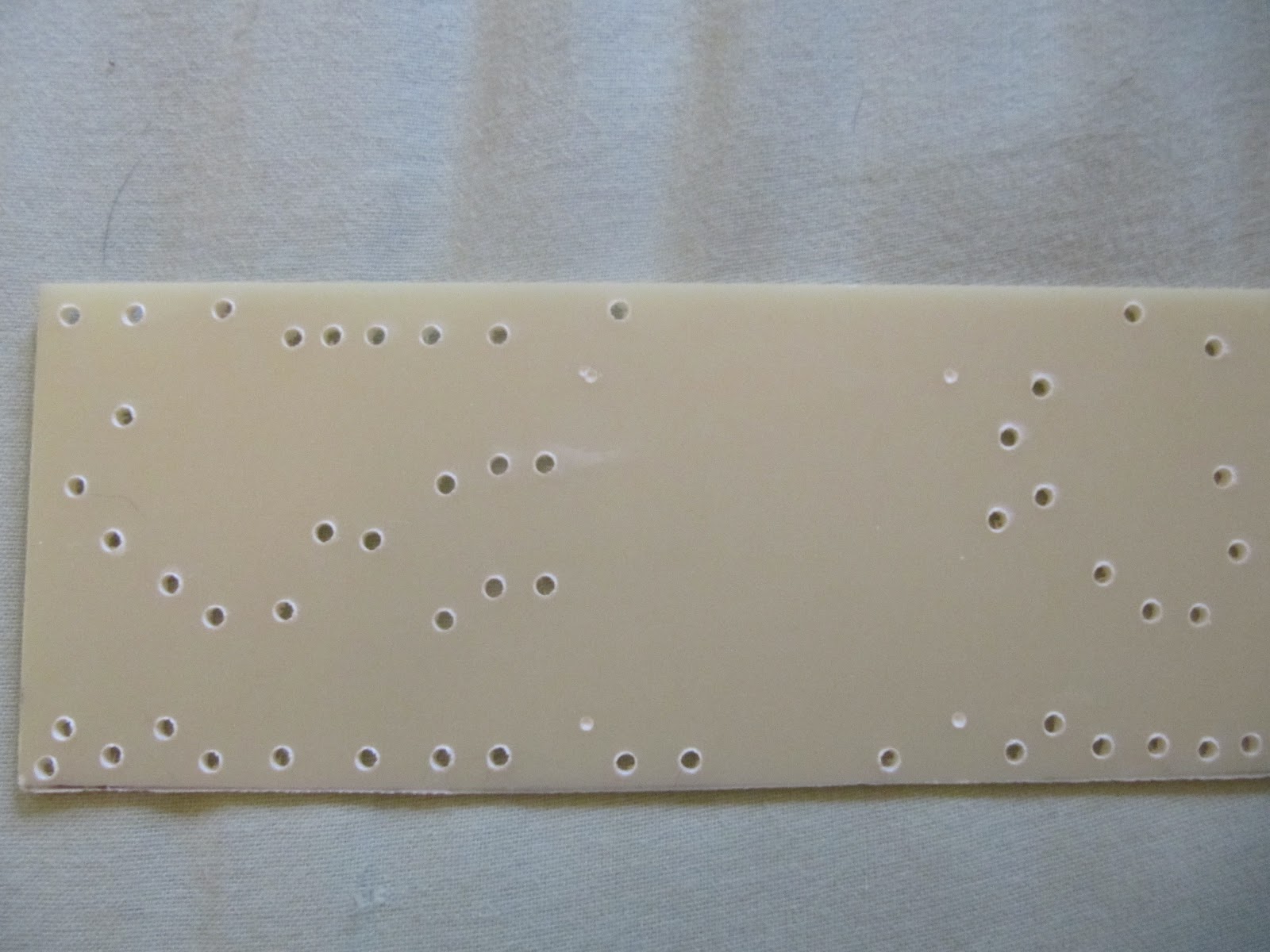
Here's what the main board (which is an impressive 20.5"x3.5") looked like prior to drilling:

I then go ahead and drill the holes suitable for the rivet-like turrets that I prefer:

Note that there are some slight (but inconsequential) irregularities in the edges and spacing. I'm typically just using hand tools for this, I don't have (or really need) a fancy setup! Anyway, after banging home all the turrets, the board looks like this:

Note the two large empty areas. If you look back at the original DIYLC layout picture, you'll see that these correspond to area where I intend to mount a couple of small PCBs right onto the turret board. The design calls for a few things like transistors, a relay, and a small chip-amp for the reverb driver that will be more happily accommodated on a PCB. So this is a hybrid approach that should allow me to take advantage of PCB where it will be best, but stick mostly with rugged, familiar, and easier-to-tweak point-to-point construction methods. The first PCB largely corresponds to components for channel switching and the reverb driver, while the second board is entirely dedicated to the solid-state low-frequency oscillator and other circuitry dedicated to the tremolo circuit. I will show later how these PCB can be hand-fabricated using the press-n'-peel method.
Here's a few shots of the (mostly) populated board:

Close-up of the input section:

Close-up of the overdrive section:

Close-up of the power section:

More soon, next up will be the boards providing the bias supply and the area around the power tubes....
Here's a link to the current schematic. There are a few component values that still remain to be tweaked, especially in the reverb/dry mix and tremolo sections, but it's close enough to the final that I've been using it as my working document.
I thought it might be useful to document my build process a little bit.
As usual, the starting schematic is drawn in LTSpice, a great freeware simulation package. Although I typically don't bother trying to simulate an entire amp of this complexity all at once, I do also make heavy use of LTSpice to simulate many of the individual subsections of the amplifier.
Once I have a schematic in-hand that is sufficiently fleshed out, I begin the process of laying out the design. I do this mainly with the excellent shareware DIY layout creator (DIYLC) software by Bancika, proprietor of the DIY-fever blog.
I use DIYLC to layout the individual boards, but also to get a good-enough idea of where all of the chassis-mounted components such as the transformers, tube sockets, and pots will go. The boards are fabricated more-or-less directly from images exported from DIYLC, but I typically will draw final drill plans for the chassis itself in another vector drawing program that is more purpose-built for that sort of thing.
Here's my overall rough layout in DIYLC as it stands right now:

I started with fabrication of the mainboard. To do this, I export a PNG image from DIYLC of the whole layout, then import it into a graphics program, then crop and scale the image to the actual size I want. I then print out this out (taping together pieces if it's larger than will fit on an 8.5"x11" paper), and tape the overlay onto G10 garolite that I have cut to size.
Here's what the main board (which is an impressive 20.5"x3.5") looked like prior to drilling:

I then go ahead and drill the holes suitable for the rivet-like turrets that I prefer:
Note that there are some slight (but inconsequential) irregularities in the edges and spacing. I'm typically just using hand tools for this, I don't have (or really need) a fancy setup! Anyway, after banging home all the turrets, the board looks like this:

Note the two large empty areas. If you look back at the original DIYLC layout picture, you'll see that these correspond to area where I intend to mount a couple of small PCBs right onto the turret board. The design calls for a few things like transistors, a relay, and a small chip-amp for the reverb driver that will be more happily accommodated on a PCB. So this is a hybrid approach that should allow me to take advantage of PCB where it will be best, but stick mostly with rugged, familiar, and easier-to-tweak point-to-point construction methods. The first PCB largely corresponds to components for channel switching and the reverb driver, while the second board is entirely dedicated to the solid-state low-frequency oscillator and other circuitry dedicated to the tremolo circuit. I will show later how these PCB can be hand-fabricated using the press-n'-peel method.
Here's a few shots of the (mostly) populated board:

Close-up of the input section:

Close-up of the overdrive section:

Close-up of the power section:

More soon, next up will be the boards providing the bias supply and the area around the power tubes....
This is a very unusual approach to things, with the PCB/turret hybrid. I look forward to following the progress.
ReplyDeleteCan I buy a ticket?
-j (tubegeek)
Hi Jer.
ReplyDeleteThanks for the comments! I think the hybrid approach will work well for this amp.. I've hand made a few PCB boards for a few pedals, so this should be no different with the exception of mounting it on a turret board instead of in a pedal enclosure.
The raffle isn't a for-profit thing, so you can't exactly "buy" a ticket... Instead, every $25 donated on my Leukemia and Lymphoma Society fundraiser page counts as one ticket. Donate more, get more chances, it's as easy as that. The link is here: http://pages.teamintraining.org/va/rnr12/pfawcetnbg
I went for $10 - run really fast, OK!
ReplyDeleteJer, Thanks very much for your generous donation! I'll run as fast as I can! If you want in on the amp raffle though, you'll need to kick in another $15 per the post above - each ticket requires a $25 donation. Are you working on anything lately? How did the Aikido inspired unit turn out? Cheers, Paul
ReplyDeleteHmm ... Aikido.... Well, I use an Aikido line stage day in day out, 6SN7's in it. That one has been built and left alone a LOOOONG time now! My most recent project, almost finished (yeah, right) has been uber-fun: my first guitar amp in a long, long time.
ReplyDeleteAs always, there's a story:
I was reading the DIY Stompbox forum a bit recently and a circuit caught my eye: it is a FET-based distortion pedal called Supreaux Deux, based on a little guitar amp, a Supro 16T. The pedal was developed on the basis of scaling down the tube voltages for FETs but keeping the original amp's circuit otherwise, and also scaling some of the filter-type components to go with the different input and output impedances of each stage. Kind of fascinating, but all it got ME interested in was in building a Supro-like little guitar amp with tubes. It's a basic little screamer, similar to a Champ in terms of simplicity but a very different circuit overall.
So then I started looking at this schematic here:
http://www.valcopages.com/Schematics/gretsch6151.pdf
This amp is similar to the Supro 16T (and supposedly identical to a 1616T) except it has a tremolo circuit, and I had been wanting to try my hand at a tremolo too.
So I was pricing out all the various components, and meanwhile I got a call from a friend: "Somebody left a tube AM/FM radio in the trash - do you want it?" Initially I was kind of lukewarm - I don't really have any idea what to do with an All American Five, line-powered heater-string radio, which is what usually seems to turn up, but I asked what tubes it had. "5Y3, 6V6 ..." he started and of course I jumped right on it - I didn't really even have to rewire parts of the power supply, it was such a perfect starter chassis for the Supro/Gretsch circuit. A nice GE 5Y3 and a few other decent tubes in it.
So that's coming along nicely - I've built it PRETTY MUCH as you see it in the schematic, the only differences are some adjusted values in the tremolo circuit to slow it down, get wider speed control, and also to add a trem intensity adjustment. And I added a switchable .33 cathode bypass to the V1B section to try and get more raunch/overdrive out of it. I tried the amp with a Strat and it didn't get nasty at all - with my P-90/humbucker/fat flatwound-equipped guitar I get a lot more signal driving the amp to begin with, but the Strat wasn't pushing it much.
The trem sounds wonderful, really great. The overdrive option isn't quite right - I may try a pentode input stage, I think I got some 6AU6's out of it when I stripped it.
So that's the latest!
I don't really need to win the raffle, I just wanted to chip in at least a little to be supportive - I'm kind of broke these days, which is one reason trashpicking parts is so attractive! Good luck on your run!
Best,
-j