Board 3 has the main rectifier diode and some circuitry for the regulated DC for the heaters. Note that I'm using for this a dual 8A 1200V "Stealth" diode in a TO-220 package... these are rectifiers with exceptionally fast and soft recovery characteristics. These are great for audio applications, as these characteristics should help nearly completely eliminate any diode switching noise or "hash". Unfortunately for you, you probably won't be able to find any. Fairchild has discontinued the dual common cathode version, and a few friends and I bought up several hundred -- pretty much all the remaining stock -- from a surplus place. Don't worry though, there's no reason you can't use a pair of the single diode versions to make a standard full wave rectifier, and these are still manufactured and available.


You are probably asking why second TO-220 package shown on the drawing isn't shown on the finished board? The other part in question is the 6.3V LDO voltage regulator for the DC heaters. As it will be dissipating significant heat, it needs to be heatsinked (bolted!) directly to the chassis. Therefore, it will actually lie underneath the board shown with the leads sticking up into the three turrets on the left hand side of the above picture. Getting it all mounted will no doubt be slightly fiddly, but some test fitting seems to indicate it shouldn't be too bad. The need to dissipate heat is also the reason that this part of the DC heater circuit is on a separate board from the board with the low voltage rectifier and reservoir cap... the surface under the other board is steel, which sucks as a heatsink. This board goes on the back panel, which is aluminum, and therefore an excellent heatsink. The DC regulator is in a fully insulated package, in case you are wondering, so no issues with bolting it directly on.
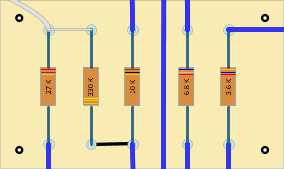
Board 4 is boring -- just a few resistors mostly for metering. You'll notice that the one on the far left is missing on the board. That's because it corresponds to R27 on the schematic, which is shown as having a value between 27K and 100K -- it needs to be selected to balance the metering, and the right value can only be chosen and soldered in once the circuit is being tested and a particular T4B is decided upon... although the compressor works just fine even if the metering is slightly wonky.

Only one board to go!! Then onto some proper drill plans.
No comments:
Post a Comment