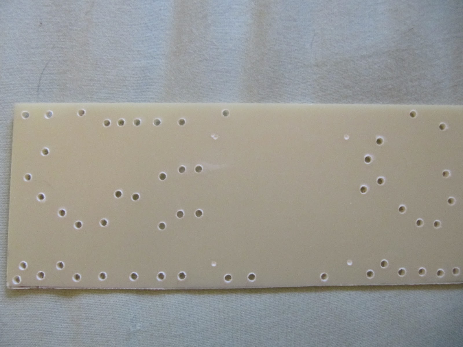
More details will come later on this integrated tube hi-fi project that I've been slowly working on since around April of this year, but which is now finally coming together. For now, here are some pictures of the build in progress. The first shows the hand-etched PCB boards mounted to the the chassis top, while the bottom shows a test fitting of the transformers and tubes. The chassis was machined and anodized to my specification by Landfall Systems out of McKinney, TX. While it was on the pricey side, I have to say that they did an amazing job, and that the quality of the workmanship was superb. They were also very nice to work with. The front and back panel will still be sent to TMI Amplification out of Alexandria, VA, as they are my unsurpassed go-to place for laser-engraving. In fact, I would have had TMI do the machining for the top as well, except that Landfall was able to offer post-machining anodization which was a really nice touch for the top.
Tube complement here is 4 x KT-88s power tubes and 2 x 6AN8 triode/pentodes for the power sections (which resemble those found in the Dynaco Mk. III but for the PSU) and 4 x 6DJ8 triodes for the preamps.
Some quick clips recorded awhile ago highlighting some of the clean sounds from the Wombat Mk. I amplifier. My brother Kelly Fawcett playing and singing. No fancy recording or EQ here, just an iPhone camera. Reverb from a Holy Grail pedal in front of the amp.
Some Jazzy/Bluesy noodling on a Strat to give you a good idea of the basic tone:
So it turns out that I was horrible about blogging this project! I managed one preliminary design post, but then nothing. But it's not because I had nothing to say, I just got busy. I actually did a pretty good job of documenting everything as the build progressed and I have plenty to share. So, I hope to redeem myself by instead starting at the end and working backwards! To make amends, I begin by offering a photo gallery of the completed unit featuring some great work by Richmond based commercial photographer Adam Ewing.
Just as a reminder, the EMP-351 is an all-tube microphone preamplifier that is based on a well-known mod of the classic AMPEX 351 reel-to-reel player that was pioneered over at Electrical Audio.
As you can see, I ended up building a dual version, which adds a few bells and whistles to the original version, including additional line level and high impedance inputs, as well as impedance selection and an attenuator bypass switches. It also includes amenities such as 48V phantom power, an output attenuator, phase switch and input selector. This particular unit is was constructed for Andrew Everding, audio engineer at Neil Finn's Roundhead Studios in Auckland, NZ.
Much of the credit for the beautiful appearance of the finished unit rightfully belongs to Mason Wolak of TMI amplification, an Alexandria, VA based company that did the laser engraving of the faceplates. Thanks also to John Morand of Sound of Music Recording Studios for helping out with the final calibration and checkout.
This post will cover the design and construction of the phantom power and DC heater filament board for the EMP-351 microphone preamp project I outlined in an earlier post.
This preamp, which is based on a well-known modification from Electric Audio of the repro and record boards in the old Ampex 351 reel-to-reel player will have relatively high gain. In fact, from the strictly hi-fi point of view, it's a bit of a silly design, since it has two full gain stages prior to an unusual phase inverter which also provides significant gain. In the standard mod, this actually necessitates amplification, then attenuation, followed by further amplification, if it is desired to keep the end-to-end gain of the circuit down to the 65-70 dB or typical required for a mic pre. Without the attenuation offered by the calibration potentiometer after the second gain stage, the end-to-end gain of the circuit would theoretically exceed 90 dB -- too much for practical use. Of course, the penalty for breaking the "no attenuation followed by amplification" rule is an increase in noise.
That issue with signal-to-noise ratio is an inevitable compromise that comes along with this kind of circuit. But it is possible to mitigate the problem, at least a bit. For instance, unlike the original unit, the EMP will employ metal film resistors throughout, which are significantly quieter than the carbon composition resistors found in the original. I also made the decision early on that this project should use high quality regulated 12.6VDC for allof the preamp tube filaments, not just the input tubes. In my experience, DC tube heaters are something that should be done right, or not at all. Unfortunately both the original Ampex and the Electric Audio mod rely on a very crude unregulated DC supply consisting of not much more than the rectifier and a big old 4000uF cap. Needless to say, there will be significant residual ripple with even three preamp tubes, and it's unworkable with the six that I need. Nowadays we can do much better.
The six preamp tube that this preamp will have is admittedly a bit of an issue. They'll be drawing a total of 900mA at 12.6VDC. While that might not seem like that much, because of the generally quite poor power factor of low-voltage supplies, it turns out that you actually need quite a bit higher rating (something like 3A, more on this shortly) in order to safely feed those six tubes nice pristine DC.
So things brings us to power transformers. If you think about it, a project like this represents a bit of an unusual situation. Since we have no current thirsty power tubes to feed, the the current requirements for our high-voltage B+ supply are quite modest -- really just a few tens of mA at very most! But the voltages are still in the high range you would normally associate with tubes. On the other hand, we have a disproportionately large thirst for current from the low voltage supply. Unfortunately, most transformers that supply plenty of current for the low voltage secondaries are also designed to provide waaay more than I need for the high voltage. This makes such transformers a bit too large and unwieldy to be practical for a fairly compact rack mountable unit. I was also not too excited about the other options involving two separate transformers. Aside from the space issue, there's the additional unwelcome complication that this unit has to able to work with both 120V/60Hz power and 230V/50Hz.. a consideration that further limited my transformer options.
The logical thing to do, therefore, was to get a transformer wound just for this job, and indeed that's what I did. That said, I also wanted a transformer design that would be flexible enough to use in the future in a variety of small projects, including potentially things involving a low-wattage power tube. In the end, this meant opting for a bit more B+ current capability than I strictly needed for this project. Also, it meant that I wanted the flexibility of being able to power tube heaters from 6.3VAC. So for my low voltage, I actually opted to have two separate 6.3V secondaries with good regulation that I can run in series for 12.6VAC or rectify for powering a 12.6VDC supply (as I will be doing for this project). The trade off here is that I could have made my life a little bit easier with respect to power factor if I had chosen a higher low-voltage secondary (say 15V), but I would have lost the flexibility of using this transformer in other contexts.
I'm having a small batch of the following transformers constructed for me by Heyboer Transformers, located in Grand Haven, MI. It's a pleasure working with the folks at Heyboer, and they come highly recommended:
Primary 115/230V
Secondary # 1 240 Volts
@ 115 mAmps
Secondary # 2 6.3 Volts
@ 3.0 Amps
Secondary # 3 6.3 Volts
@ 3.0 Amps
Drop me a line if you are interested in one of these transformers, I'll have at least a couple left from this order that I don't have immediate plans for.
Before we go any further, here's a link to the (PDF format) schematic for the filament and phantom board. As you can see from the schematic, this was actually drawn in LTSpice, my favourite (and free!) circuit simulator software. I have, in fact, confirmed the proper operation of this circuit with the simulator. NOTE: a fuse is not shown on this, but is obligatory for any real-world implementation.
A couple of points.. the phantom power is derived from a fairly standard voltage quadrupler circuit. In principle, I suppose I could have used a voltage tripler, and referenced it to the output of the main rectifier. But the inherently half-wave operation of a tripler wasn't appealing, both in terms of the unbalanced current established in the transformer, and in terms of the limited available current. The choice of the TL783C adjustable high voltage regulator, was influenced by Douglas Self's recommendation of this part in his excellent book "Small Signal Audio Design". Every serious audio electronics hobbyist or audio professional should own this book.
As to the heater filaments portion of the design, it's fairly standard, and follows the treatment given by Merlin Blencowe in his excellent (but sadly now out-of-print) book on tube amp power supply design. This will be the first time I've used the Micrel MIC29300-12WT regulator, which is a promising looking high current, low dropout part that is newly available from Mouser. Unlike the TL783, the MIC29400-12WT will be dissipating 3W or so of power, so will be heat-sinked to the aluminum chassis.
Now, of course, a schematic only gets you so far. Long time readers of this blog know that I'm a big fan of the freeware program DIYLC (do-it-yourself layout creator). I do most of my layouts, both for hand-etched PCBs and for entire large amps, using DIYLC. Because of the regulator chips and the small adjustment pot, it made a lot more sense to design this one as a PCB rather than as a turret board. So here's what the PCB layout looked like once it was implemented in DIYLC:
Here's what the mask looks like with no components. Resize this image to 4.75" x 3.75" if you wish to etch your own board based on this. Incidentally, for anyone who wants to build this, I strongly recommend that you chose 105degC rated low-impedance ("low-Z") capacitors for the large electrolytic (1000uF and 4700uF) shown on the schematic.
For one-off or small numbers of boards, I use the Press n' Peel Blue Transfer paper method in conjunction with ferric chloride etching. I wouldn't want to do a dozen boards this way, but it's fine for a couple. Here's a helpful YouTube video made by someone else that demonstrates the method:
Here's what my board looked like at the various stages of this method. First is with the Press-'n-Peel ironed on:
Next, we dump it in the ferric chloride solution and swirl it around for forty minutes or so until all of the exposed copper is etched off:
After it comes out, it'll look this initially. Note that the Press-'n-Peel is still stuck to the copper areas:
This needs to be gently scrubbed off to reveal the copper traces:
You can stop here, but I find that soldering is made much easier if the copper is first coated with a layer of tin. I do this by an application of a product called "Liquid Tin". It's easy to use and works great:
At this point, you are ready to drill the board and mount the components! Once again, here's what the finished board looks like!
Everything here is attached except for the 12V regulator, which as I mentioned will be heat sinked to the aluminum chassis when the board is installed. Needless to say, it's extremely satisfying to start with just a concept, and end up with its physical realization in your hand.
Stay tuned, next time we'll begin looking at the main circuit, and follow along the construction of one of the main turret boards!
I realized today that it's been nearly a year since this blog has
been updated, but that doesn't mean that Wombat Amps hasn't been busy!
On the contrary, we've now launched an improved web site,
I've established a formal Wombat Amps workspace in a building that also
houses dozens of bands -- as a consequence I've been doing a fair
amount of repair work -- more than I had really intended actually.
Nevertheless, I have been working on some interesting projects,
including a cool custom amp that was recently completed and a solid
state equalizer.. But details of these just haven't made it to the blog
for want of time.
However, I'm working on a new microphone preamplifier project that I'm really excited about, and I
hope to document a fairly complete build log here. This mic preamp was commissioned by Andrew Everding, perhaps best known as the keyboard player for the band Thursday. However, with Thursday currently on hiatus, Andrew has moved on to audio engineering, and is currently located in Auckland, New Zealand, where is an audio engineer working directly with Neil Finn (of Crowded House fame) at Neil's well-known Roundhead Studios.
In any case, Andrew is a big fan of tube microphone preamps based on modification of old Ampex reel-to-reel players. As a tube aficionado, this makes perfect sense to me - in a world now flooded with sterile-sounding ultra-low distortion preamp choices, more and more musicians are realizing that a bit of distortion, of the right kind, can be just the ticket for producing a warm, full sound.
One of the preferred platforms for the mod community has been the amplifier from Ampex 351 reel-to-reel player, as shown above. In fact, there's a fair amount of documentation online (especially at the Electric Audio forum, courtesy of Greg Norman), describing how to mod one of these units into a preamp. So why not just mod one of these, and be done? Well, it turns out that there are a number of good reasons. First, the Ampex 351 is now highly sought after, and prices for these units have skyrocketed. You can easily pay $1300 or more for one on fleaBay, and what you get will be in uncertain condition. And this is before the mod process, which turns out to be not at all straightforward. These were constructed on now crufty old first-generation PCBs that are prone to traces lifting from accumulated moisture, and are not particularly amenable to modification. Also, there is a ton of other circuitry in there that gets in the way and is unneeded after the mod, you're for sure going to have to replace all the power supply capacitors anyway, etc., etc.. Even after you go through all the trouble, you're still going to be left with just a single preamp, not a dual. So you'd need to do this all twice to get a dual setup! And this single would not really be optimised in terms of layout, ground scheme, noise, etc. It also wouldn't provide modern amenities such as phantom power and fully regulated DC tube heaters, at least not without having to do a bunch of extra work. But aside from all that, the Ampex is still a pretty damn good reel-to-reel player, and I just hate seeing beautiful old gear being canabilized in that way. So the decision was made early on in the process to scratch-build from new components a dual preamp that stays true to its heritage but incorporates just the components necessary for a preamp. In addition, it should incorporate features such as phantom power and regulated DC tube heater supply, and do it all in an attractive 3U rack-mountable package. Here's the design brief:
Dual microphone preamp inspired by the Ampex 351 circuit;
Each section to combine elements of the Record and Repro
boards of the original in a manner similar to the Electric
Audio preamp mod;
Tube complement of each section will be 2 x 12AX7 and 1 x
12AU7;
Tubes provided will be New Old Stock (NOS) selected for
low noise, gain, and balance;
Custom wound transformers audio transformers from Sowter UK;
Chuck D'Aloia doing his thing at the 2012 LA amp show
As you those that follow this blog now, I spend most of my spare time inhaling solder fumes working on my various amp and effects projects. But once in awhile -- not as often as I should -- I get the urge to actually, you know, play some guitar. The problem is, I'm just not all that good, and not particularly imaginative. Like a lot of guys, I seem to have a hard time breaking out of familiar patterns and riffs. So it's a wonderful tonic when something comes along that can help you break out of a rut and introduce you to some new ideas. This blog post is about one of those discoveries. Chuck D'Aloia is a really great player -- I've long admired his playing, which I first came across when checking out various amplifier demos on the intertubes. But, as it turns out, Chuck is a first rate teacher as well. I highly recommend that you check out his "Blues with Brains" lesson series. Here's a little preview on YouTube, showing how to take on a basic blues progression with a little bit of a more interesting harmonic approach. I bought the rest of the lessons, and it just gets better from there. It was money well spent.. Thanks Chuck!
The Fender Champ is an iconic amplifier with roots going all the way back to 1948. Noted for the simplicity of its circuit and controls (in many versions, just a simple volume knob), it's hard to imagine a simpler or lower-cost tube amplifier. This perhaps explains why, over the years, many manufacturers have produced amplifiers with circuits that vary from that found in the Champ in only incidental ways, and why the circuit is of ongoing interest to DIY hobbyists. Well, that and the great tube tone! While a wide variety of Champ circuit variants have been produced by Fender, the 1958 Tweed-era 5F1 is perhaps the most enduring. However, the layout employed in the 5F1 has a primitive ground scheme, and the amplifier is not particularly quiet. I've been asked a few times how I would lay out such an amplifier with a more modern approach. Note that while it employs a "bussed stars" approach, it has only *one* attachment point to the chassis for the audio circuit right at the input jack (although please note that any real-world circuit MUST also incorporate a completely sound safety earth connection from the third prong / ground of the mains power to the chassis). The input and output jacks themselves should be insulated. The circuit shown here is fairly true to the original. If I were to build one for myself, I would undoubtedly incorporate a few more changes to further modernize things to improve noise performance and reliability -- but purists would undoubtedly complain. Please note that the suggested layout is a draught only, and should be thoroughly error-checked before using it as a launching pad.
Cam DiNunzio and the folks over at Black Iris have been busy lately! If you've been following this blog, you know that Black Iris commissioned both the EQP-1A tube equalizer and the LA-2A optical compressor described at length in earlier posts here. Cam has told me that these have been used in the recording of the music for quite a few television commercials that you may have seen over the last year or so. But my favourite is a jingle that that Black Iris did recently for the Saatchi & Saatchi Agency for their Toyota Prius "Hum" ads. Cam used both the Wombat Amps EQP-1A and the LA-2A for tracking the acoustic guitar and the vocals, and evidently the agency "continuously commended the 'warm' and 'natural' sound of the recording". Cool! This 30 second spot came out awhile ago, back in September I think:
However, I just became aware of this newer 60 second spot, which is what prompted me to post this today:
I've been quiet for awhile here, but there should be a flurry of posts coming in the next few weeks. I've been working on-and-off on a solid-state studio equalizer project based on the EQ section from the the old-school Trident S-80. This is based largely on circuit boards developed by PeterC over on group DIY. According to current plans, the unit will be a quad channel EQ.
In the meantime, here are links to a couple of brief videos I recorded this summer before sending the Quest amplifier off to David Morin, the winner of the LLS amp Raffle.
First is a general demo of some of the clean sounds from the Quest amp. In the end, I was quite happy with how sparkly the cleans can be. There is a decent amount also of clean headroom, albeit less than would be expected in an amp with global negative feedback. I had wanted also to record a demo of the overdrive channel, but the crappy camera mic just wasn't up to the job. Apologies for the rudimentary playing.
Next is a demo of how the tremolo sounds, which I thought would be of interest, since the method by which the volume is modulated is, I think, somewhat novel (the transistor based LFO varies the current through a vactrol, which acts the series resistance in front of a virtual-earth mixer type tube stage, which, aside from the mixing function, is also configured to provide some additional gain for the reverb recovery. As I mention at the end of the video, I think it worked out pretty well.
The raffle for the Wombat Amps Quest amplifier was conducted today using the RandomPicker.com website. You can see the details and the protocol that was used.
I'm excited to announce that David Morin of Monmouth, ME is the lucky winner!
Many thanks to everyone that so generously donated to support the Leukemia and Lymphoma Society and this project. Special thanks are also in order to my collaborators from the Gothik Amps consortium that so graciously donated time and materials for the amp project.
This includes Ben Sykora of Sykora Custom Tube Amps, for his donation of a beautiful hand-built head cabinet, Mason Atom Wolak of TMI amplification, for the engraved faceplate, and Brian Schmittling of DirtyDawg Amps for the custom aluminum amp chassis.
In the end, we raised almost $3800 for cancer research, with donations coming from five countries (USA, Canada, Slovakia, Australia, and the United Kingdom) and three continents.
Hey everyone! I know it has been quiet here, but this almost always means that I have been busy amp building instead of blogging. Just to update everyone, on 3 June, I ran the San Diego half-marathon with the Leukemia and Lymphoma Society's "Team in Training". Although I ended up dropping down from my originally planned full marathon to the half, and I didn't set any speed records this time, I'm proud to say that this was the sixth event I have completed with Team in Training as either a participant or as a fundraising mentor. With over 2500 Team in Training participants at San Diego, it was a great experience, and at this one event alone the LLS raised over $7.3 million for cancer research. To those of you that have donated, thank you very much -- you are making a real difference. For those of you that have not yet donated and wish to get in on the amplifier raffle, the fundraising page is here. Remember, each $25 donated counts as a ticket in the amp raffle!
Team Wombat celebrates! When anyone asks I tell them, "Yes, I *did* win, thank you for asking!"
So the run is over, and the fundraising will also soon be coming to an end. With only a couple of days left before the amplifier raffle (the raffle is happening on this Sunday 24 June!), I wanted to post a few more more build pictures before the amplifier is totally completed. Right now, virtually everything is done, except for tweaking the final wiring of the sockets and the pots, which I should be able to knock off on Saturday morning. After that, we'll be ready for first fire-up and final tweaking.
The guts, awaiting final harnessing up.
Close-up of the solid-state tremolo board. It's a good illustration of the hybrid turret and PCB approach I tried out for the first time with this amp. The board with the green capacitors is actually a hand-fabricated PCB, while the surrounding main board is traditional turret board construction. So far, I'm pretty happy with how this worked out.
Close up of the main board. The TO-220 packages visible in the foreground are the ultra-low noise "Stealth" rectifier, and the STF3NK80Z MOSFET that at the heart of the capacitor multiplier on the screen supply.
Something else that I've tried that's slightly unusual on this amp is to have a dedicated turret board for all of the power tube associated circuitry. I got tired of the screen grid resistors vibrating around, and it just made sense for this layout.
This afternoon, UPS delivered on my doorstep the beautiful cherry case constructed by Ben Sykora that he generously donated to support my amp raffle to benefit the Leukemia and Lymphoma Society. Also arriving in the package was the awesome custom 12-gauge aluminum chassis donated by Brian Schmittling of DirtyDawg Amps, which is definitely the hobbyist's go-to place for guitar chassis. So now all the boards are constructed, all the components are in-hand and we are now ready to enter the final assembly and wiring phase. It won't be long now!
That said, I'm leaving for the race in San Diego this Friday, so it's time to admit that things have fallen a little bit behind schedule. The original plan was to hold the amplifier raffle immediately following the race. However, as it's clear now that the amp just won't be ready by then, I've decided to delay the amplifier raffle until Sunday, 24 June. That's three weeks after the day of the race, which will give me time to fully complete the amplifier prior to the drawing. I've also settled on a method to transparently and independently conduct the raffle. I will be using the services of the RandomPicker website.
Oh, and one final thing! The amplifier has a name, courtesy of John Hannon over at AX84... henceforth it shall be known as the Wombat Amps "Quest"!
I posted some in-progress pictures of the raffle amp head cabinet donated by Ben Sykora of Sykora Custom Tube Amps, but now it's completed and we're ready for the next phase! The final finish on the cherry wood turned out really nicely. Check out Ben's amazing handiwork. :
In other news, I've finished fabricating all the point-to-point boards, and I also had a chance this week to fab the PCB for the channel switching relay and reverb driver. Now all that's left is the PCB for the tremolo circuit. I'll post some build log pics of the latest progress here as soon as I get a few more minutes.
Progress continues on the raffle amplifier. Here's some build-log snaps of the power tube board. Again, I'm doing something a bit different here. Rather than just use terminal strips to hang components directly off the tube pins, I've opted this time for the different approach of a separate board with socket-sized holes that can be positioned directly over the tube sockets. I tried this first for my LA-2A build, and it worked out pretty well. It allows for a slightly more "3D" approach to the components around the tube socket. Heater wiring, for instance will be running flush with the chassis, well separated from the sensitive bits. I've also been becoming unhappy with the practice of directly soldering the screen stop resistors directly between pins 4 and 6 supported only by their leads. This should prevent them from rattling around. The board is 6"x2.25", with 1" diameter holes above the power tubes.
Ready to go. Just missing the (optional) 3kV R3000 protection diodes:
I've been quiet, but busy -- with now just a few weeks until the raffle, construction of the raffle amplifier is now well underway.
Here's a link to the current schematic. There are a few component values that still remain to be tweaked, especially in the reverb/dry mix and tremolo sections, but it's close enough to the final that I've been using it as my working document.
I thought it might be useful to document my build process a little bit.
As usual, the starting schematic is drawn in LTSpice, a great freeware simulation package. Although I typically don't bother trying to simulate an entire amp of this complexity all at once, I do also make heavy use of LTSpice to simulate many of the individual subsections of the amplifier.
Once I have a schematic in-hand that is sufficiently fleshed out, I begin the process of laying out the design. I do this mainly with the excellent shareware DIY layout creator (DIYLC) software by Bancika, proprietor of the DIY-fever blog.
I use DIYLC to layout the individual boards, but also to get a good-enough idea of where all of the chassis-mounted components such as the transformers, tube sockets, and pots will go. The boards are fabricated more-or-less directly from images exported from DIYLC, but I typically will draw final drill plans for the chassis itself in another vector drawing program that is more purpose-built for that sort of thing.
Here's my overall rough layout in DIYLC as it stands right now:
I started with fabrication of the mainboard. To do this, I export a PNG image from DIYLC of the whole layout, then import it into a graphics program, then crop and scale the image to the actual size I want. I then print out this out (taping together pieces if it's larger than will fit on an 8.5"x11" paper), and tape the overlay onto G10 garolite that I have cut to size.
Here's what the main board (which is an impressive 20.5"x3.5") looked like prior to drilling:
I then go ahead and drill the holes suitable for the rivet-like turrets that I prefer:
Note that there are some slight (but inconsequential) irregularities in the edges and spacing. I'm typically just using hand tools for this, I don't have (or really need) a fancy setup! Anyway, after banging home all the turrets, the board looks like this:
Note the two large empty areas. If you look back at the original DIYLC layout picture, you'll see that these correspond to area where I intend to mount a couple of small PCBs right onto the turret board. The design calls for a few things like transistors, a relay, and a small chip-amp for the reverb driver that will be more happily accommodated on a PCB. So this is a hybrid approach that should allow me to take advantage of PCB where it will be best, but stick mostly with rugged, familiar, and easier-to-tweak point-to-point construction methods. The first PCB largely corresponds to components for channel switching and the reverb driver, while the second board is entirely dedicated to the solid-state low-frequency oscillator and other circuitry dedicated to the tremolo circuit. I will show later how these PCB can be hand-fabricated using the press-n'-peel method.
Here's a few shots of the (mostly) populated board:
Close-up of the input section:
Close-up of the overdrive section:
Close-up of the power section:
More soon, next up will be the boards providing the bias supply and the area around the power tubes....
While I was away away on vacation, the bits and pieces of the amplifier I am creating for my raffle in support of the my Team-in-Training fundraiser to benefit the Leukemia and Lymphoma Society are starting to arrive, and things are starting to come together! A few more weeks and we'll have a beautiful custom amplifier ready for some lucky winner. To whet your appetite, here are some preliminary photographs (there's still a bit of sanding and finishing to do) of the custom Cherry wood cabinet being constructed (and generously donated to the cause) by my amp-building crony Ben Sykora of Sykora Custom Tube Amps!
In addition, the OT and the PT have arrived. The OT is a Heyboer-wound TO-26 unit from Allen Amplification. This is a great OT that I have used previously in a Tremolux-style build. But since it is beefier and has 50% more core steel than a typical tweed 6V6 OT, I've found that it works well also for 6L6GB or 5881 tubes with an intentional impedance mismatch. The PT is an AS-2T300 300V 200VA toroidal unit from Antek that is suitable for use both in the US and UK/Europe/Australia, with a simple wiring change.... I also upped for the nice anodized steel case for the PT, as I do with my Grail amplifiers.. so it should look pretty slick too!
Thanks again Ben, this cab is going to be amazing!
Thursday, March 15, 2012
Team Wombat will be running the 2012 San Diego Marathon, and we are raffling off an custom built amplifier in support of the Leukemia and Lymphoma Society as part of the deal! Please considering making a tax-deductible donation on my LLS fundraising page -- every $25 donated counts as one ticket in the amplifier raffle to be held 3 June 2012. Please see the fundraising thread on AX84 for full details. And never mind that the picture shows a honey badger, not a Wombat! Good luck to my Team in Training team mates running the Shamrock Marathon in Virginia Beach VA this weekend!
I had a chance finally to finish and box up both my updated Rangemaster and Humless A/B/Y box projects, both of which incorporate circuit ideas from the excellent geofex website.
Here's the final, corrected PCB art. The board dimensions are 1.25" H x 2.3" wide:
A pair of etched PCBs made with the Press n' Peel blue method:
Here's a drill plan for a standard "B" size enclosure. This image should be printed at 5.25" W x 4.625" H:
Rangemaster guts (right hand box):
Finished Rangemaster (right hand box):
I'll update this soon with the final schematic.
The bottom line is that I'm very happy with the final result. At the end of the day, it is (and sounds like) a true germanium PNP Rangemaster -- but is one that will get along happily with a standard polarity pedal power supply. The Millennium bypass is also working well - with the 2N5460 JFET, there seems to be no perceptible delay in the lighting of the LED once the switch is engaged, and is, so far as I can tell, otherwise completely sonically transparent.
I'll fill out the details on this in a bit, for now I'm just posting the PCB layout for an ABY box splitter based on circuit details from Geofex. The circuit as shown here seems to have a bit of noise in the input of whichever amp is not currently selected...putting this up to get some feedback from the forum folks, more later.